ProbeFC
Power supply units (PSUs) in NAS and SAN probes are numbered 1 and 2, from left to right, as viewed when facing the back panel. The PSUs are hot-swappable.
Note
Before configuring hardware probes, it is recommended that any Brocade and/or Cisco SAN Integrations are configured and have completed their initial discoveries.
Follow these steps to create any of the hardware probes.
From the Settings page, click Performance Probe Inventory to access Probes and Integrations.
The Performance Probe Inventory page is displayed.
The column headings are defined in the following table:
Table 227. Performance Probe Inventory ParametersColumn Heading
Definition
Probe Name
The name you assign to the probe
IP Address
IP address of the probe
Probe Type
Type of hardware probe, for example, ProbeFC-16G-24
Status
Status of the probe: Subscribed, Unsubscribed, Offline, or Faulted (subscribed, but not receiving data).
Version
Firmware version, for example, 6.2.1
Messages
Status information
Unassociated Links
Number of “unassociated links” (links that IO is unable to autoplace); this value is a whole number.
Select ProbeFC from the New drop down menu.
ProbeFC refers to all probes in the ProbeFC family.
Enter the IP address of the probe and click Next.
You can use the IO UI to change a Performance Probe’s IP address if the initial configuration (Initial IP) is already set. IP addresses can be changed if the old and new IP addresses can be routed from the appliance.
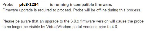
If the probe firmware is incompatible with IO, a message is displayed that identifies that the probe is running incompatible firmware and the Upgrade button displays on the page.
Proceed to Step 4.
If the probe firmware is compatible with IO, the Create New ProbeFC page displays. Proceed to Step 5.
Follow these steps to upgrade the probe firmware.
Click Upgrade to upgrade the firmware.
The “Upgrading message” and Close button appear.

Click Close.
The Hardware Probes Inventory page displays, with the probe listed in the inventory. Notice the that Version column in the inventory shows the firmware version, followed by
Upgrading...A firmware upgrade takes approximately fifteen minutes, during which time you are not able to configure the probe.
When the upgrade is finished, click the probe in the inventory list to display the Create New ProbeFC page. Proceed to Step 5.
Assuming that your probe is running compatible firmware, the Create New ProbeFC page displays. This page is pre-populated with information discovered regarding the probe of the specified IP address. Use the scroll bar to navigate the full Create New ProbeFC page.
Verify the probe configuration.
With the exception of the Subscription status, the information regarding the probe on the Create New ProbeFC page is auto-detected from the hardware probe configuration (and was input from either the probe LCD screen or the Configuration Wizard of the probe).
Descriptions of the parameters on this page are as follows:
Table 228. Create Hardware Probe ParametersParameter
Description
Probe Name
Hostname of the probe
Serial Number
Probe ID
Probe Type
Type of probe: ProbeFC8, ProbeFC8-HD, ProbeFC8-HD48, ProbeFC-16G-24, ProbeFC-16G-12
Version
Firmware version of the probe
Network Address
Network settings (static or DHCP) of the probe
NTP Server Address
NTP server configuration for the probe, can specify up to three
DNS
DNS server setting for the probe, typically two
MAC Address
Network port MAC address
Subscription
Subscribe or unsubscribe the probe, values are Subscribed (default) or Unsubscribed
Enable Locator LED
Enable the locator LED on the probe
The following are descriptions for the column headings in the Ports section of the page:
Table 229. Column Headings in the Ports SectionColumn Heading
Definition
Port
Port Number.
Link Mode
Auto or manual link association, auto is the default.
Link
Link association of the link, values are Discovering or WWN_dev <--> WWN_switch, meaning that the association between the device and switch has been discovered, (WWN_dev is the WWN of the device, and WWN_switch is the WWN of the switch).
Note
Before Link Associations can be configured the following conditions must be met:
Brocade and/or Cisco SAN Integrations must have completed their discoveries
Probes must be subscribed for at least 10 minutes to allow NTP to synchronize and provide relevant data
Hardware Diagnostics for each Probe must show no link errors
Link License
Type of license, values are Auto Assign, None, 4 G, 8 G, 16G, where Auto Assign chooses the license based on link speed.
Configured Speed
Configured speed, values are: no sync, Auto Sense (sense automatically), 1 Gb, 2 Gb, 4 Gb, 8 Gb and 16 Gb.
If set to Auto Sense, IO applies the license type to the discovered speed. If no licenses are available for the specific link speed observed, IO attempts to assign a higher link speed license (if available).
Current Speed
Current detected speed, values are: no sync,1 Gb, 2 Gb, 4 Gb, 8 G, 16 Gb, 24 Gb.
Bulk Configuration
Allows for bulk configuration of ports
In the Ports section of the page, select each port that you want to configure by checking the check box by the port number.
If you want to configure all the selected ports with the same Link License and Configured Speed values, you can do a “Bulk Configuration” of multiple ports. Skip to Step 9.
Choose the Link License for each selected port by clicking on the corresponding Link License column and choosing the link license value from the drop down menu.
Choose the Configured Speed for each selected port by clicking on the corresponding Configured Speed column and choosing the configured speed from the drop down menu.
After selecting multiple ports to be configured, click Bulk Configuration.
The Bulk Configure Ports dialog box displays.
Choose the License Speed and Configured Speed for the selected ports. Click OK.
Verify that the settings that you chose as well as the pre-populated ones are correct.
Click Save on the Create New ProbeFC page to commit the changes and create the new hardware probe.
The Hardware Probes Inventory page displays, with your newly created probe listed in the inventory list.